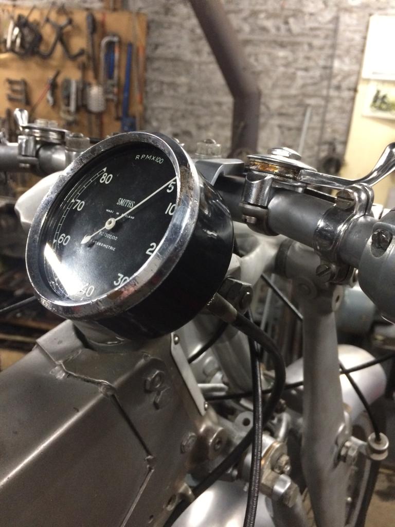
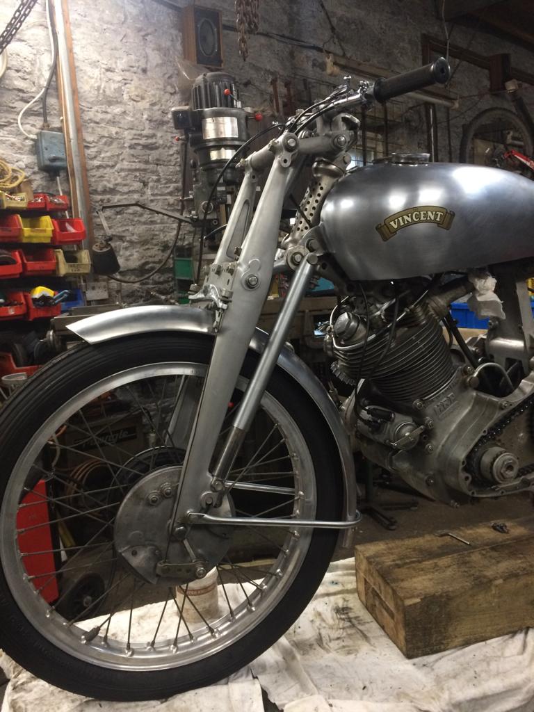
In this post I will give instructions on how to mate with a 1940s Smiths chronometric tachometer… 🧑🏻🏫
Okay, that was a lame joke BUT such is the patinated beauty of this instrument that just looking at it positively generates an erection…
The re-profiled bracket.
The bracket was re-profiled as outlined in a previous post. It was then sent out to be dull chromium plated for the second time…
Oh no, I’ve “premmed”…
That looks so in-keeping with all this restoration has been focused on: the icing on the cake, a veritable visual smorgasbord, a riot of the senses, an orgy of ocular splendour, a classic motorcycle aficionado’s wet dream, a… I could wax lyrical ad infinitum…
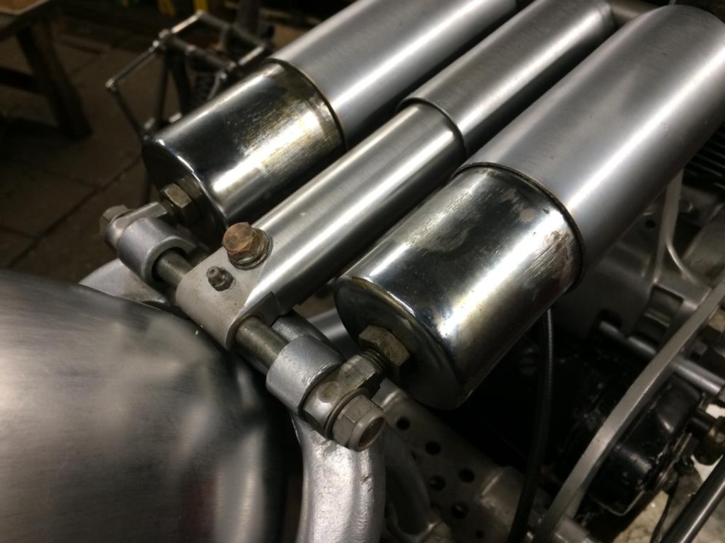
In the meantime, Bert has been wrestling with the profile of the exhaust pipe… Details of this to follow.
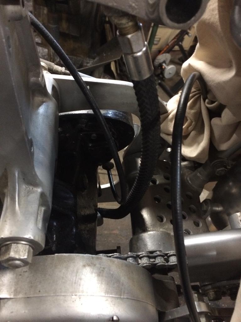
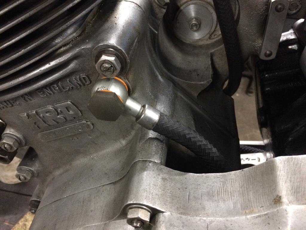
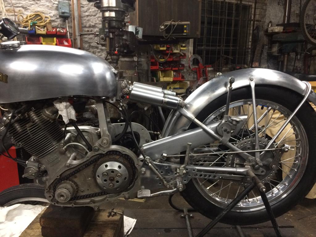
Sourcing the correct herringbone patterned oil/fuel pipe has not been easy… There are still some stocks of 3/8″ ID pipe available but stocks of 5/16″ ID pipe have dried up and none is currently being manufactured.
Oil feed.
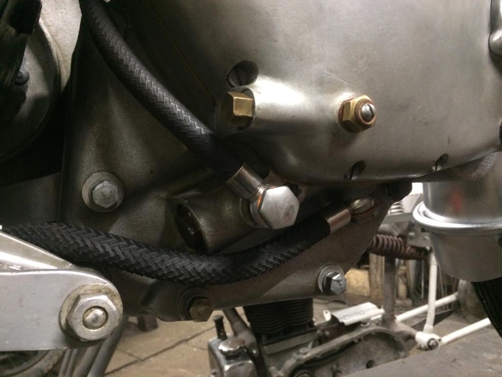
The correct run of the oil feed pipe was determined to be as above. We decided to stick with 3/8″ pipe for this as all the feed fittings present on the machine were sized to accommodate this ID – and many of them appeared ancient and possibly original to the bike. Below some shots of the other pipework in place.
Jubilee clip compression mark visible but no correct pipe available so this will have to remain!
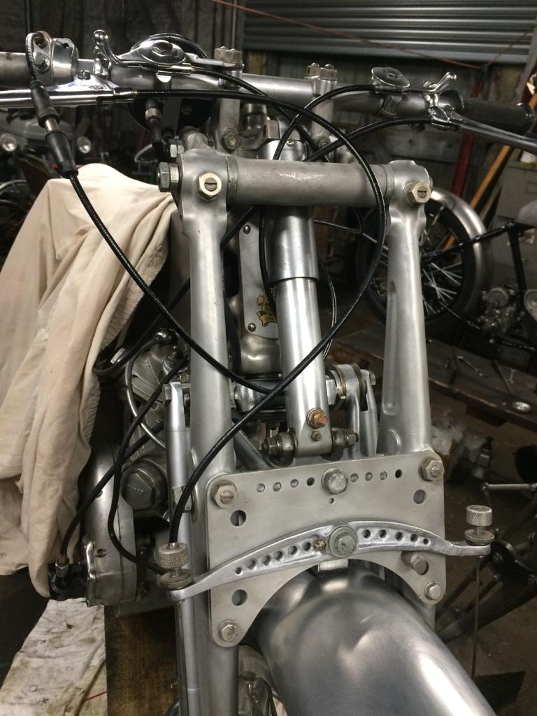
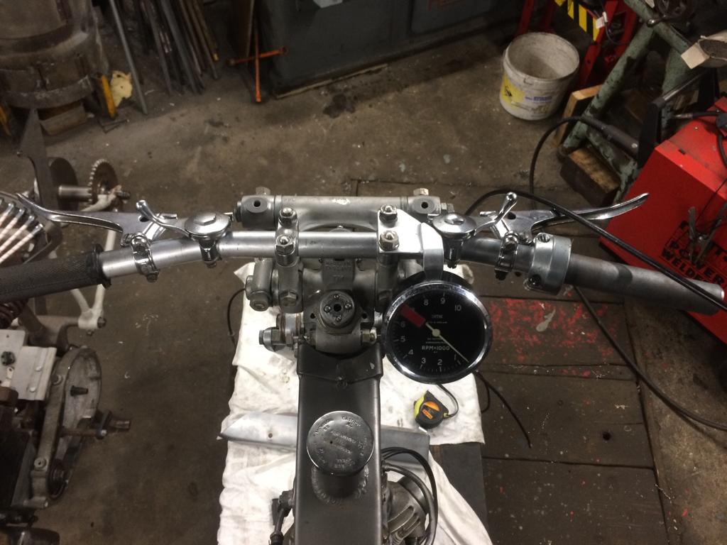
The title is self-explanatory so I’ll just annotate the photos.
The period cables look incredible.
Some are likely to question the run of the throttle cable…
Running the throttle cable over the brake lever like that looks weird. In-period some were set up like this though and it’s actually the best route for the cable. We might revert to running it behind the lever later on – it can be changed easily enough.
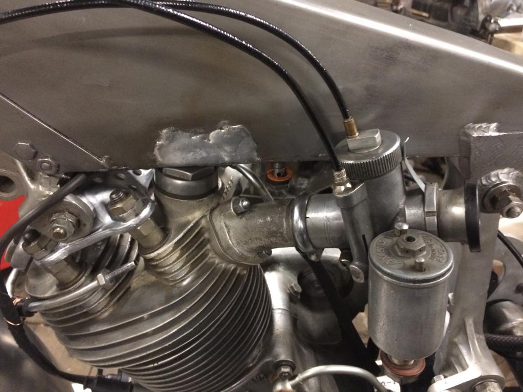
The carb is now fitted. The solder on the UFM marks where the remote float bracket was.
The HT lead and pickup cable have been taped together with cloth tape as per period photos.
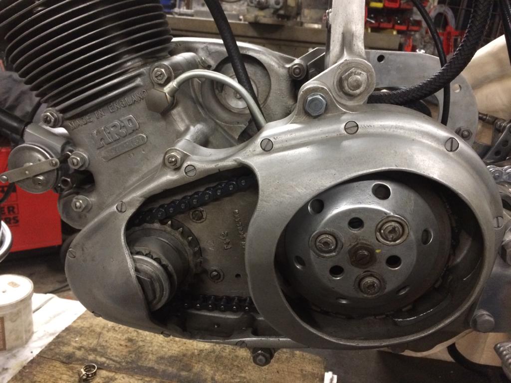
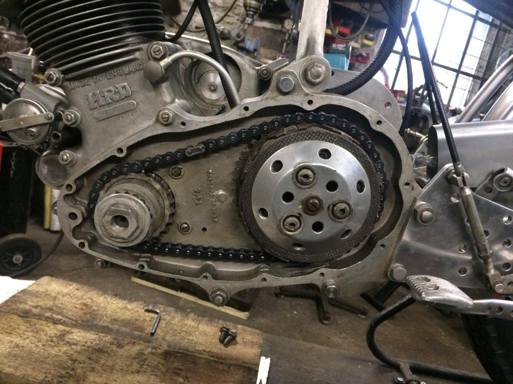
The primary chain case cover is now in place and looking purposeful.
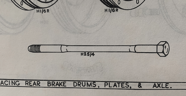
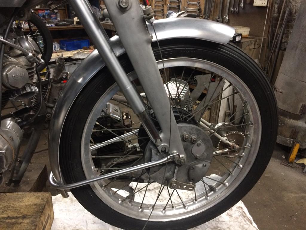
All Vincent racers were supplied with Axle bolts rather than the T-bar arrangement seen on the roadgoing models. This is quite an obscure component and falls into the “not a lot of people know that” category… This rare racing part is depicted in the Spare Parts List.
We can see that these are waisted for lightness.
And not “wasted” as some are wont to write! 🤤
2751 was missing these important parts and they needed to be made for the project. Where to start… No drawings or dimensions exist and few original items survive. Many years ago Vincent legend Big Sid sent me some pics of some NOS racings parts that he held and was looking to sell – these, I believe, ended up being used in the Gunga Din rebuild.
These three images appear to depict the just the one axle – an H25/3AS front item. In addition, I had a few pics of this component in situ on various bikes.
The above two images show the bolt/nut clearly – this is the Ehret Black Lightning. Note the protruding tapered “lead”.
The rear of the same bike.
Here seen on another Grey Flash.
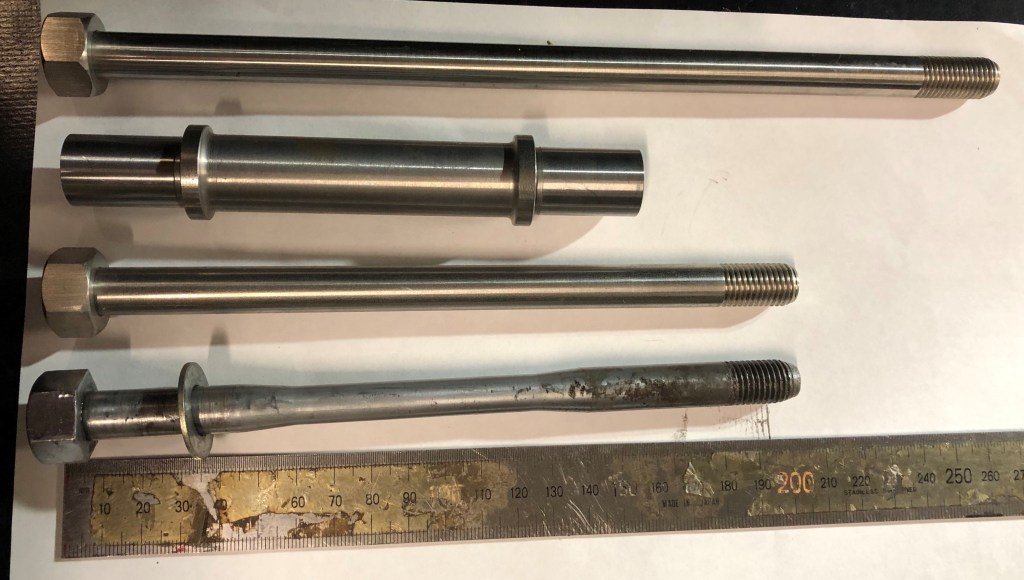
Working in conjunction with David Dunfey, and cross-referencing our available info, a drawing was made and tweaked until we were as satisfied as could be. Down in Australia, Stuart Penn kindly pulled one of the axles on his uncle’s BL and sent me the dimensions.
This is also a front bolt. Above it are two Series D axle bolts and a hollow axle, for purposes of comparison.
Yes, the Series D also utilises bolts rather than the T-bar configuration – these are available new from the VOCS and could be adapted? Well, no… In addition to the waisted centre portion, the threaded portion features a tapered end or “lead” to enable the axle to be pushed home and locate quickly under racing conditions. This taper means that the racing items are a little bit longer than they would need to be on a roadgoing bike. In addition, the bolt head is actually a nut brazed into place…
First the waisted axle shafts were machined up.
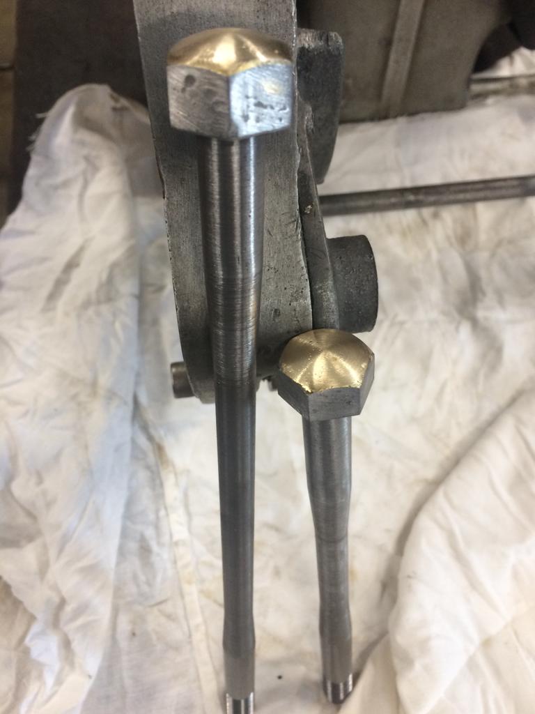
Nuts brazed on and dressed.
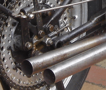
In situ. Note repair to rear fork.
A lot of research was required to enable these axle bolts to be manufactured – the waisted portion had to be right to prevent catastrophic failure. Machined from high tensile steel, they will now need to be finished and would originally have been cadmium plated. I would like to thank David Dunfey, Stuart Penn and Franco for their assistance. 🙏🏻
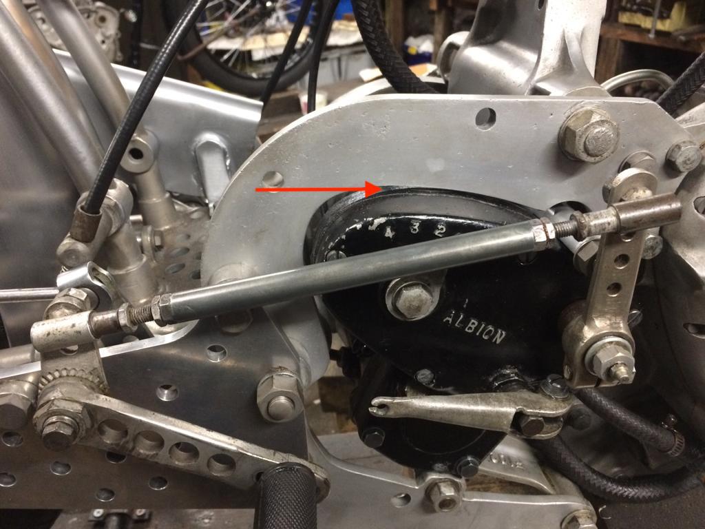
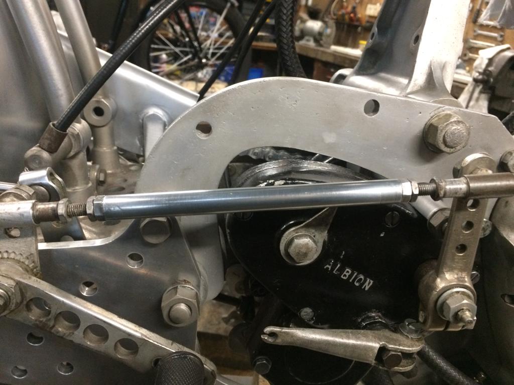
Throughout its long racing career 2751 suffered many incidents that left their mark on the surviving original components. The magnesium gearbox casing bears “witness” marks from where primary chain slackness had been adjusted to the point where the casing was pushed up against the G50/2 pivot bearing plate.
Unacceptably close.
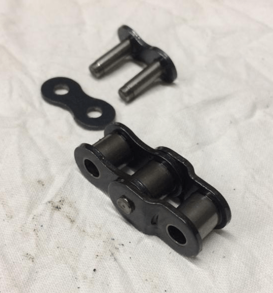
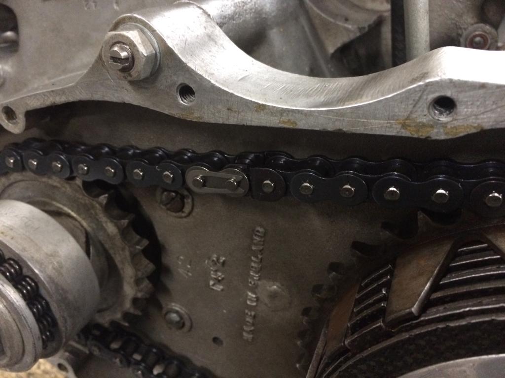
Once a new primary chain had been fitted, it became obvious that more clearance was needed as the top of the gearbox casing was perilously close to the plate at nearly full adjustment. Bert got around this issue by fitting a cranked link, shortening the primary chain by just one roller.
The cranked link and soft riveting link.
Fitted.
There is a now a nice gap twixt gearbox case and plate enabling future adjustment to account for chain wear.
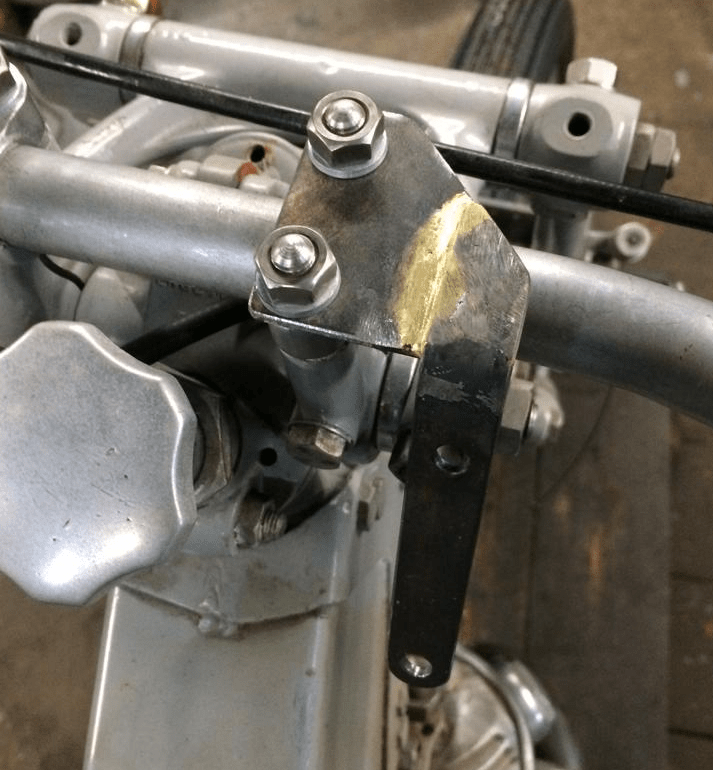
Bert Carefully replicated the the tacho bracket from the E.M.G. Stevens/F. Griffin drawing held on file by the VOC. The Club has taken great pains to create a database of accurate drawings for every part employed in all Vincent HRD motorcycles and “The Drawings Project” is still, as far as I’m aware, an ongoing process. Data was compared, correlated and precise drawings rendered, correcting many discrepancies previously encountered. Prior to the commencement of this project, many Vincent “pattern” parts were often found to not perform in conjunction with Works-made spare parts – there were all manner of issues that caused a lot of aggravation for enthusiasts as well as the small batch manufacturers involved in their production. So it was with the utmost confidence that Bert was able to fabricate a tachometer bracket exactly as the “Obscure Components” drawing.
A portion of which is shown here…
Freshly fabricated.
This seemed fairly straightforward and the drawing enabled Bert to make it precisely. It did look a little out-of-keeping when compared to other parts on the bike though. For example, why don’t the radii match those of the handlebar clamps? It looked ill-thought-out to our eyes and at odds with the levels of detail visible on other parts of the machine. Anyway, off it went for dull chromium plating…
Back from the platers.
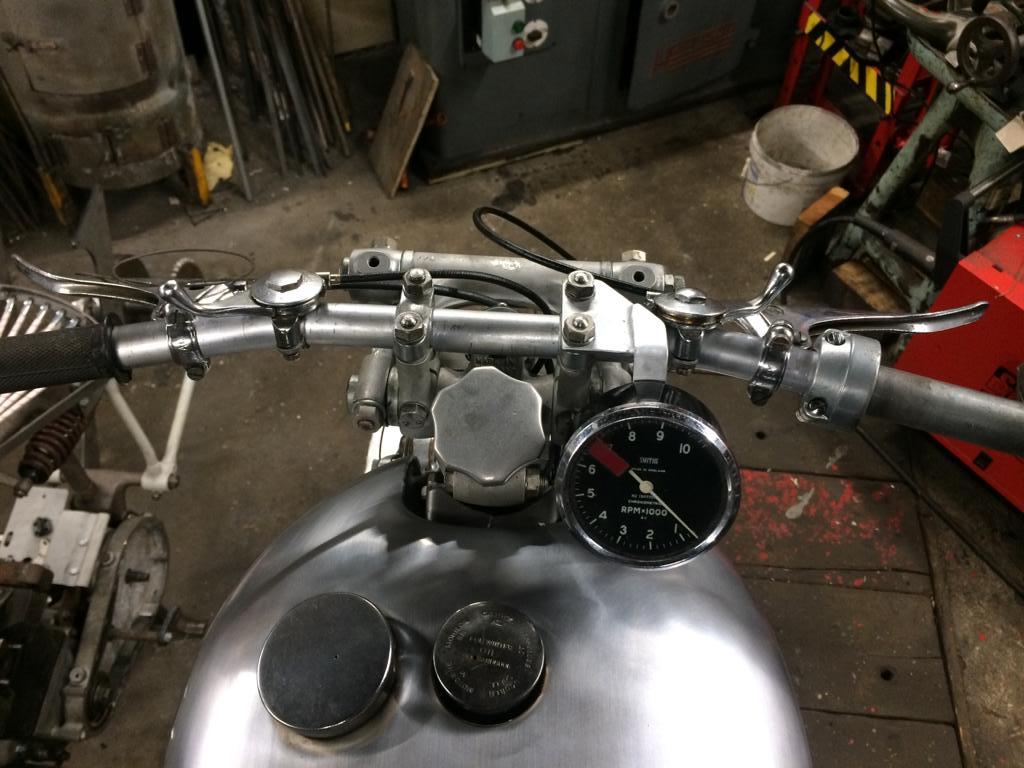
Once back and bolted into place Bert attached the old (incorrect) tacho head to see what it looked like. His first comment was that it was going to position the unit “bloody close” to the tank…
This looks wrong…
2751
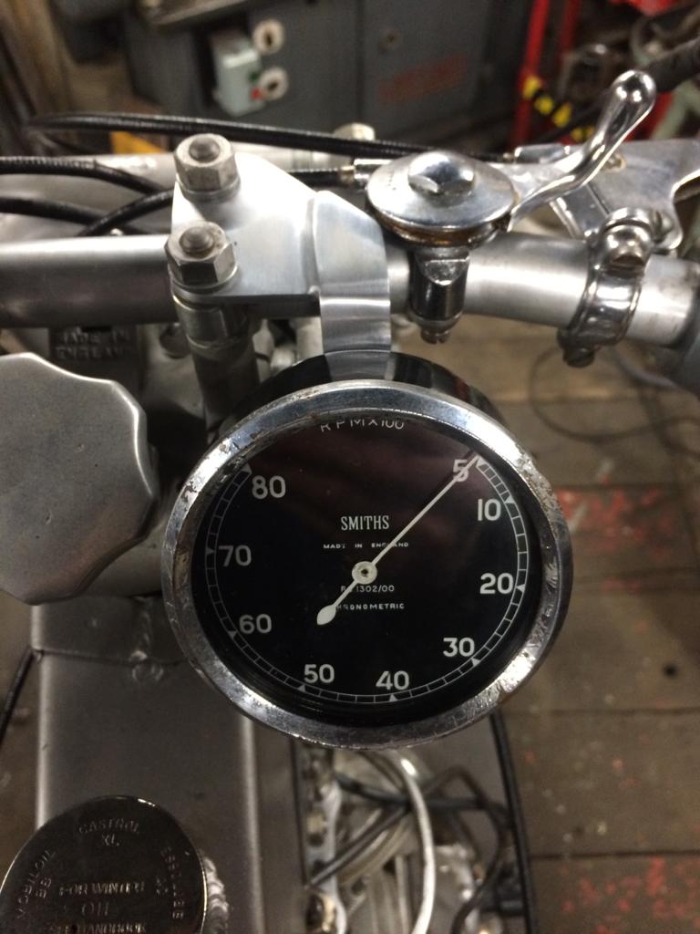
Period shots of 2751 and other GFs show the tachometers angled less… I ran this past David Dunfey and he kindly sent me a photo of a genuine bracket and mentioned that the “Obscure Components” drawing may have been based on a bracket employed by John Surtees on his personal Grey Flash racer.
Right!! (photo courtesy of David Dunfey)
The radii match that of the handlebar clamps – of course! A lesser angle too… Bert magnanimously agree to perform the necessary modifications and the re-worked bracket will now need to be re-plated.
That’s better!
Top banana!
Bit of a head-scratcher this one! So “obscure” is this part that no-one has ever questioned the drawing and there is very little call for such a bracket anyway.
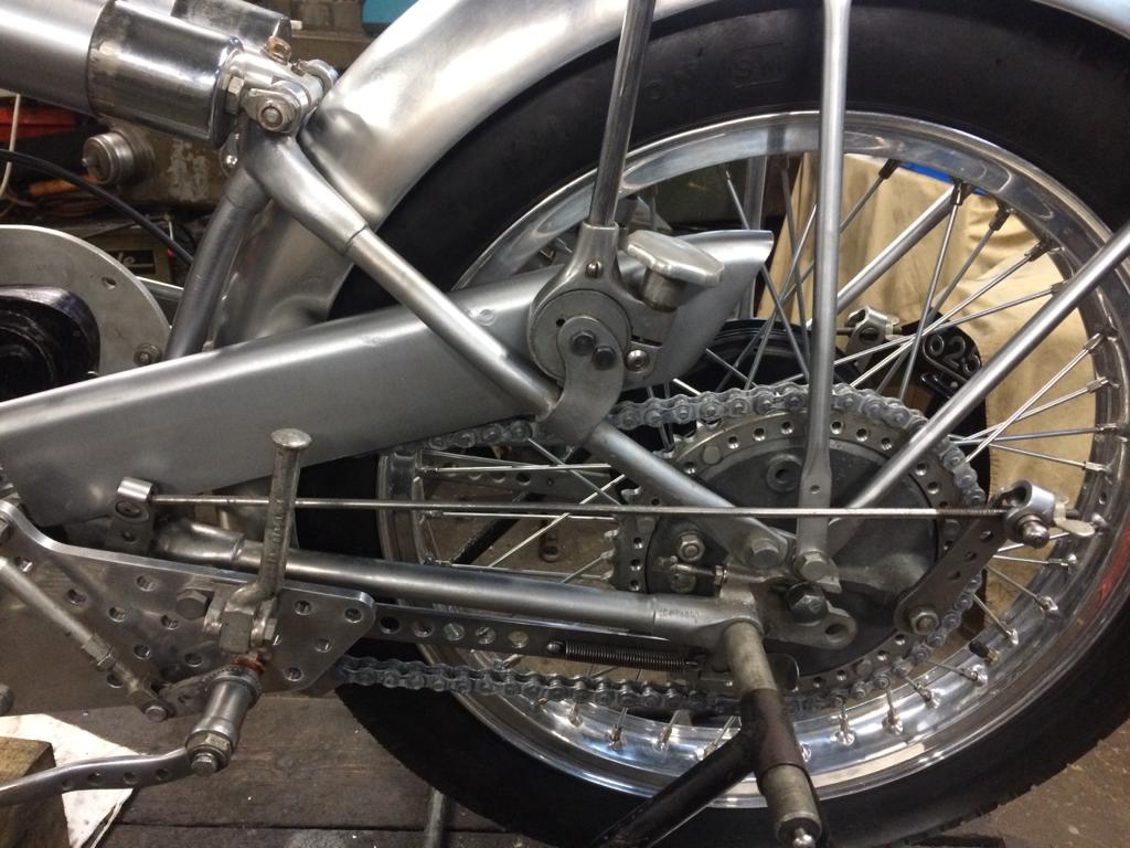
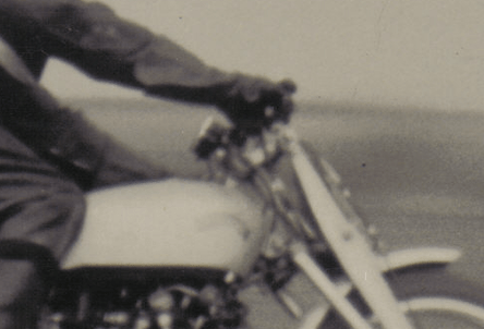
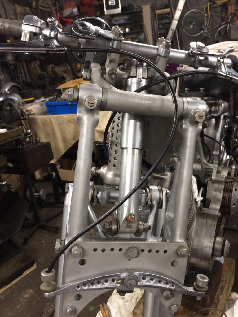
Bert and I have been studying period photos of 2751 in order to ascertain how to route the cables and their lovely fabric sheaths.
In all the period photos the brake beam balance stop is on the “wrong” side and we have installed it this way round.
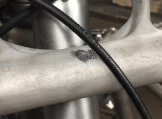
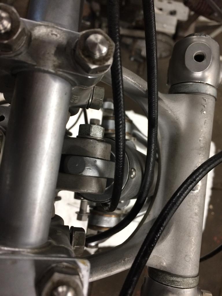
The mark in question…
The upper fork link bears a “witness mark” where the sheath covering has rubbed off exposing the metal underneath – this was most useful helping us find the right path for the front brake cable.
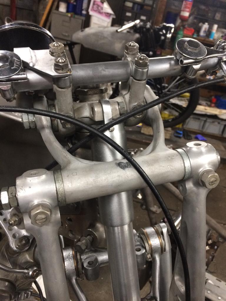
Much care has to be taken with the routing of these cables to: (i) ensure that they do not foul when the forks are on full lock and (ii) are not pulled taught when the forks are fully compressed. If this happened then the front brake would likely be be actuated and the wheel would lock resulting in a situation too terrible to contemplate…
Rigged up and locked in the opposite direction.
With the cable and ferrule in place.
The view from above.
And down the drive side of the UFM.
We are currently awaiting sundry parts back from the platers and the rubber hoses/ferrules to make up the oil and fuel pipes.